News Letter
Sign Up & get 33% off your first order
Enter your preferred name & e-mail to subscribe
No suitable mailing lists could be found


Solid State programmable solenoid valve cyclic timers offer adjustable and fully automated Power ON and OFF control for solenoid valves, typically used for compressor drain and pneumatic air line drain systems. The cyclic timer is designed to fit between the solenoid valve DIN 43650 coil and electrical DIN connector normally associated with well-made solenoid valves. Obviously these are not suited to solenoid valves with flying lead wires as there is no DIN43650 electrical connection.
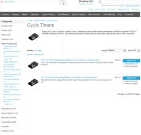
Buy Solenoid timers / Timer controllers and other time dependant valves Online.
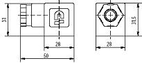
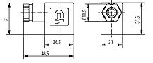
Solid State solenoid valve programmable timers fit directly between the electrical DIN connector (either a DIN 43650A  square see left-hand side or DIN 43650B rectangular look at the right-hand side) and the solenoid valve coil and can be installed simply by removing the solenoid valve
  DIN connector and inserting the cyclic timer to the solenoid valve coil and replacing the DIN connector to the timer. Thus, the cycle timer, single shot or delay timer is simply sandwiched between coil and connector.
The cyclic timer is now between the power supply and coil and can now control the ON/OFF cycle of the solenoid valve, drawing its power supply from the same source. Most cyclic timers will be multi voltage compatible and will work from any voltage from 24 volts to 240 volts in either DC (Direct Current) or AC (Alternating Current).
The industry standard solid state timer will offer a Power ON LED Light and a POWER OFF LED Light, so users will know if power is supplied and if the solenoid valve is energised, with an additional Manual Test Button to kick the timer into the Power On into valve cycle.
Helpful Hint: It is advisable to check the voltage supply is compatible with your solid state timer and to pay attention to the power consumption of the solenoid valve, as most standard solid state timers are usually limited to controlling a maximum of 10 Amps. Special voltages and current options are also available, and it is always wise to check electrical compatibility for all parts.
More information on electric cyclic timers can be found here.
There are an unlimited range of time sequences available, however we have detailed below the most commonly requested.
|
|
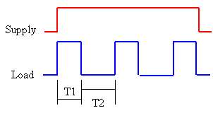
Repeat Cycle TimerUpon application of power, the timer resets, enters the ON state for a period T1, then switches OFF for a period T2. This cycle repeats until power is removed.
|
|
| Power Off Cycle Adjustment Time | Power On Cycle Adjustment Time |
Our Part Number Other manufacturers will vary |
| 0.5 to 45 minutes (as above) | 0.5 to 10 Seconds | TEC22 |
| 25 to 150 minutes | 0.5 to 10 Seconds | TEC22N02 |
| 0.5 to 45 Minutes | 20 to 300 milliseconds | TEC22N03 |
| 0.5 to 10 Seconds | 0.5 to 45 Minutes | TEC22N04 |
| 0.5 to 60 Minutes | 0.3 to 5 Minutes | TEC22N05 |
Solid state timers can be supplied to offer a single electrical shot, a delay time then an electrical shot, delay repeat electrical cycle, single cycle timers are also available. Below are the technical main points of these more specialist timers.
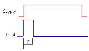 |
Single Shot TimerUpon application of power supply, the timer resets, enters the POWER ON to solenoid valve state for a period T, then switches POWER OFF to solenoid valve indefinitely until the power supply is removed. When power is reapplied, the cycle restarts. |
|
|
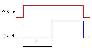
Delay TimerUpon application of power, the timer resets, enters the POWER OFF to solenoid valve state for a period T, then switches POWER ON to solenoid valve indefinitely until the power supply is removed. When power is reapplied the cycle restarts. |
|
|
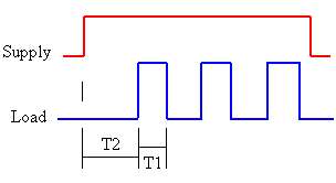
Delayed Repeat Cycle TimerUpon application of power the timer resets and enters the POWER OFF to solenoid valve state for a period T2, then switches POWER ON to solenoid valve for a period T1. This sequence repeats until power is removed. |
|
|
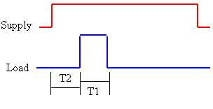
Single Cycle TimerUpon application of power the timer enters the POWER OFF to solenoid valve state for a period T2, then switches POWER ON to solenoid valve for a period T1. It then switches OFF & remains OFF indefinitely. |
Solid State Solenoid Valve slot in Timers fit between the solenoid valve coil and electrical DIN connector, however there are several industry standard sizes and types of coil and DIN connector to consider and choosing the correct size if of paramount importance when choosing your timer. The most common two types are as follows:
|
|
DIN 43650A
are most commonly used for general purpose solenoid valves 28mm square fitment
|
|
|
DIN 43650B
21mm wide rectangular fitment. common size on compressor drain
|
A catalouge of articles covering all aspects of solenoid valves
Enter your preferred name & e-mail to subscribe