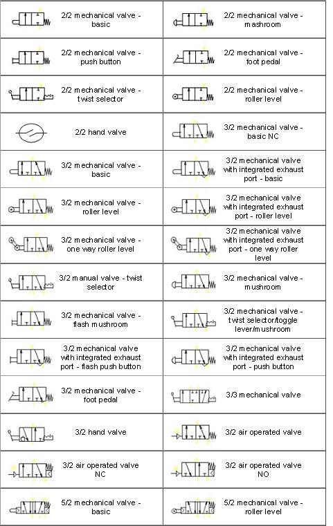
Common Solenoid Valve and other Pneumatic symbols.
a detailed view of pneumatic circuit symbols and their meaning. Valve symbols including solenoid valve symbols are those that are in common use.
Solenoid Valve Symbols:
Solenoid Valve and other Pneumatic System Common Symbols
and how they relate to solenoid valves and pneumatic equipment.
|
|
 2/2 Valve 2/2 Valve
2 Ports 2 Positions
|
 3/2 Valve 3/2 Valve
3 Ports 2 Positions
|
 4/2 Valve 4/2 Valve
4 Ports 2 Positions
|
 4/3 Valve 4/3 Valve
4 Ports 3 Positions
|
 5/2 Valve 5/2 Valve
5 Ports 2 Positions
|
|
 5/3 Valve 5/3 Valve
5 Ports 3 Positions
|
 Accumulator Accumulator
|
 Air Dryer Air Dryer
|
 Air Motor Air Motor
Flow One Direction
|
 Air Motor Air Motor
Flow Two Directions
|
|
 Check Valve Check Valve
Spring Closed
|
 Compressor Compressor
|
 Cylinder Cylinder
Spring Return
|
 Cylinder Cylinder
Double Acting Double Rod
|
 Cylinder Cylinder
Double Acting
Single Fixed Cushion
|
|
 Cylinder Cylinder
Double Acting
Two Adjustable Cushions
|
 Differential Pressure Differential Pressure
|
 Direction Of Flow Direction Of Flow
|
 Exhaust Line / Control Line Exhaust Line / Control Line
|
 Filters Filters
and
Regulators
|
|
 Filter Filter
Automatic Drain
|
 Filter Filter
Manual Drain
|
 Fixed Restriction Fixed Restriction
|
 Flixible Hose Line Flixible Hose Line
|
 Flow Control Valve Flow Control Valve
|
|
 Flow Gauge Flow Gauge
|
 Lever Lever
|
 Lines Connected Lines Connected
|
 Lines Crossing Lines Crossing
|
 Lubricator Lubricator
|
|
 Muscular Control Muscular Control
|
 One Bypass Flow Path One Bypass Flow Path
and Two Closed Ports
|
 One Flow Path One Flow Path
|
 Pedal or Treadle Pedal or Treadle
|
 Pilot Pressure Pilot Pressure
External
|
|
 Pilot Pressure Pilot Pressure
Internal
|
 Plugged Port Plugged Port
|
 Plunger or Position Indicator Plunger or Position Indicator
|
 Pneumatic Pneumatic
|
 Pressure Pressure
Actuated Switch
|
|
 Pressure Gauge Pressure Gauge
|
 Pressure Regulator Adjustable Pressure Regulator Adjustable
Non Relieving
|
 Pressure Regulator Adjustable Pressure Regulator Adjustable
Self Relieving
|
 Push Button Push Button
|
 Quick Quick
Connect
Coupling
|
|
 Roller Roller
|
 Roller One Way Roller One Way
|
 Shuttle Valve Shuttle Valve
|
 Silencer Silencer
|
|
|
 Solenoid and Pilot Manual Over Ride and Pilot Solenoid and Pilot Manual Over Ride and Pilot
|
 Solenoid Single Winding Solenoid Single Winding
|
|
 Spring Spring
|
 Two Closed Ports Two Closed Ports
|
|
 Two Distinct Positions Two Distinct Positions
and One Transitory Centre Position
|
 Two Flow Paths Two Flow Paths
|
 Two Flow Paths Two Flow Paths
and
One Closed Port
|
 Two Flow Paths Two Flow Paths
with
Cross Connection
|
 Vacuum Vacuum
Pump
|
|
 Variable restriction Variable restriction
|
 Working Line Working Line
|
|
|
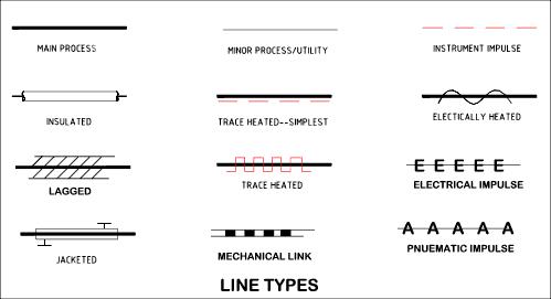
The following symbols are generally in accordance with BS1553-1 and BS5070
Different Line Types.
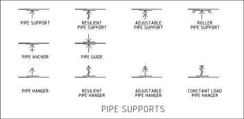
Pipe Support Symbols
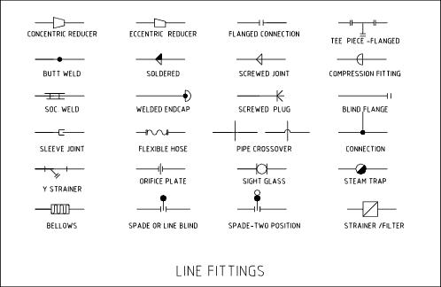
Symbols for fitting and representations.
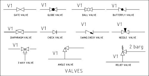
Symbols for Valves
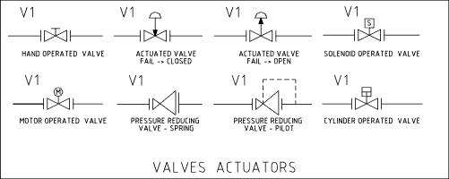
Symbols for Valve Actuators
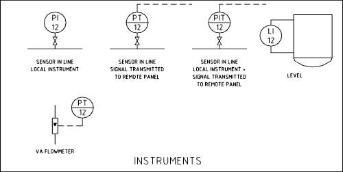
Symbols for Instruments
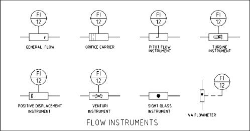
Symbols for Flow Instruments
Instrument Indentifiers
|
Measured Variable
|
Type of Conditioner
|
Type of Component
|
|
F = Flow
|
R = Recorder
|
T = Transmitter
|
|
L = Level
|
I = Indicator
|
M = Modifier
|
|
P = Pressure
|
C = Controller
|
E = Element
|
|
Q = Quantity
|
A = Alarm
|
|
|
T = Temperature
|
|
Connexion Solenoid Valve symbols from the UK's premier solenoid valve suppliers
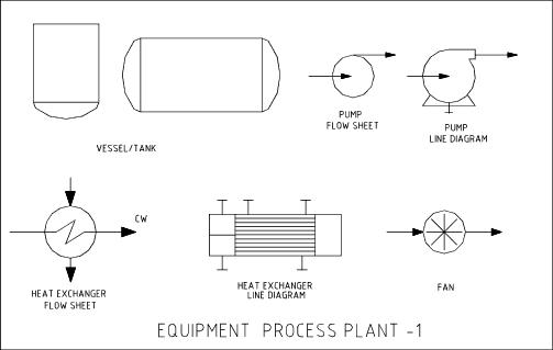
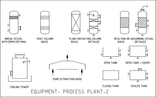
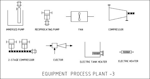
Symbols for Process Equipment
|
The levels of detail for process equipment relates to the schematic type produced. A process flow sheet will only show basic levels of technical information sufficient to highlight essential process flow paths. An engineering line diagram of P and ID will show a lot more detailed comprehensive information and technical detail.
Equipment Process Plant -1
Equipment Process Plant - 2
Equipment Process Plant - 3
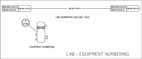
Line tags and equipment identification.
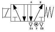
Reading Pneumatic Schematic Symbols
5/2 Valve has 5 ports and 2 possible conditions
1.) B is pressurized and A is exhausted.
2.) A is pressurized and B is exhausted.
When the solenoid is NOT energized the B port is pressurized. The spring symbol defines the valve position at rest.
The Block
The block symbolizes the possible valve functions or positions. Example: A 5/2 valve schematic will be illustrated with 2 blocks describing two valve functions or positions/ A 5/3 valve schematic will show three blocks describing 3 possible valve functions.
The Actuator.
(Solenoid) Symbol
Pneumatic valves can be operated in several ways. Hand operated (including levers and push and or push pull buttons) : Air piloted (operated remotely by pneumatic signals) : Solenoid (directly actuated with electronic signals)
Exhaust Port Symbol
The inverted triangle symbol Denotes an exhaust port. The letters EA indicate this is the exhaust port for the A circuit. Ebin turn indicated the exhaust port for the B circuit.
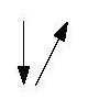
The Arrows
The arrow symbols illustrate the direction of gasses flowing into and out of the valve ports. Gas pressure is supplied from port P. Depending on which of the valve blocks is in function, the gas is directed to port A or B as shown by the arrows.
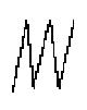
The return spring
The spring symbol defines the “at Rest” position of the solenoid valve. The spring “pushes” from the side it is drawn on and places the right side block diagram of the valve in function.
The T Symbol
This symbol indicates that a port is closed and is neither passing or exhausting gas.
Pressure of air supply symbol
This symbol indicates the air supply port, in addition to this the letter P or the number 1 also indicated the air supply port.